

1 Introduction
Ever since the framework of isogeometric analysis method is established(Hughes et al., 2005), the isogeometric method that employs the same basis functions as used in a CAD model has shown many advantages over standard finite element methods. The geometric approximation which is inherent in the mesh could lead to accuracy problems in response analysis and more adversely in design sensitivity analysis.
The isogeometric method has a major feature such as the CAD based parameterization of field variables in an isoparametric manner and thus requires no further communication with the CAD systems during refinement processes. Refinement schemes are extensively discussed(Cottrell et al., 2007) as the analogues of h-, p-, and hp- refinements in standard finite element methods. Even though a mesh is constructed, further refinement requires communication with the CAD system during design iterations, which has been one of major reasons that prevent the active industrial application of the shape optimization method. To apply the isogeometric analysis to shape design optimization problems, accurate design sensitivity analysis (DSA) is essential. Based on the shape design sensitivity theory, the applicability and accuracy of the isogeometric shape DSA method for the displacement and stress measures are shown(Cho and Ha, 2000).
When using the conventional finite element method, the inter-element continuity of design space is not guaranteed so that the normal vector and curvature information are not accurate enough. On the other hand, in the isogeometric sensitivity analysis, these are continuous over the whole design space so that accurate shape sensitivity can be obtained. Despite these several advantages, there is a critical drawback that local refinements are not possible in the conventional isogeometric method due to the tensor product nature of NURBS basis functions. To overcome the drawback, a local refinement scheme using multiple patches and h-refinement relation is proposed (Cottrell et al., 2007), an adaptive local refinement technique based on hierarchical B-splines is presented(Vuong AV et al., 2011) and the interface continuity of multi- patch shell is studied(Ha and Noh, 2018).
The local refinement scheme using multiple patches and h-refinement is extended to a continuum-based adjoint isogeometric DSA for plane elasticity problems in this paper. Since locally refined in the region of interest, more accurate sensitivity results are expected when compared with those of the conventional isogeometric model having the same number of degrees of freedom. Across the interface between NURBS patches, the C0 continuity is also imposed on the displacement sensitivity through the same stiffness matrix as used in the isogeometric analysis.
2 Isogeometric Analysis and DSA
In this chapter, isogeometric analysis framework based on the NURBS is explained. A local refinement scheme using multiple patches, named multi resolution approach are introduced. It is shown that the NURBS functions of higher continuity offer much more compact representation of the shape sensitivity expressions and have profound effects on the shape sensitivity. And some numerical examples are presented to demonstrate the accuracy of isogeometric analysis and sensitivity results by comparing with the analytic and the finite difference solutions.
2.1 NURBS basis function
In the isogeometric analysis, the solution space is represented in terms of the same basis functions as used to represent the geometry. Consider a knot vector in one dimensional space, which is the set of knots in a parametric space.(1)
where n is the number of control points and p is the order of basis function. The B-spline basis functions are defined, recursively, as(2)(3)
Using the B-spline basis function and weight wi, the NURBS basis function, is also defined by(4)
For a given pairs n of p-th order NURBS basis function and the corresponding control point, the NURBS curve is obtained by(5)
In the same way of constructing the NURBS curve, taking a tensor product of coordinates, multidimensional NURBS is defined as(6)
where the rational basis function is defined as(7)
2.2 Knot refinement
For the knot refinement of NURBS model, two schemes are available; Boehm algorithm and Oslo algorithm. Oslo algorithms is explained only in this paper. But resultant curves are identical to each other regardless of the choice of algorithm.
Given a knot vector , let be a new knot vector where multiple new knots are inserted. From the original control points , the (n + m) control points are formed by(8)
where the transformation components are given recursively as,(9)(10)
This procedure is only applicable to the B-spline model where all the weights are identical. For the NURBS basis functions, the refinement matrix Tp should be modified considering the different weights for the NURBS basis functions,(11)
2.3 Local refinement scheme
Consider the local refinement shown in Fig. 1. The bottom left corner is the region of interest to be locally refined as shown in Fig. 1(a).
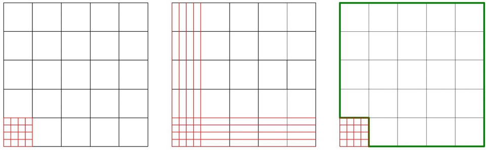
During the knot refinement procedure, unwanted degrees of freedom could be made as shown in Fig. 1(b) due to the tensor product property of NURBS. Fig. 1(c) shows the schematic of multi-resolution analysis using multiple patches. The whole domain is divided into two regions; the fine region(f: red lines) and the coarse region(c: green lines). Along the interface between patches in single region, the number of control points is equal and the control points are naturally shared in both patches. In the multi-resolution analysis, however, the number of control points along the interface between the regions is generally not equal as shown Fig. 2.
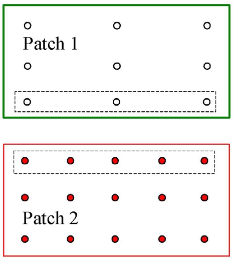
To impose a displacement compatibility conditions on the interface, h-refinement relation is utilized. At the interface, the following geometric relation for the control points should hold.(12)
where Tp,w is the refinement matrix of Eq. (12). In
the same manner, the refinement relation should hold for the nodal displacement coefficients at the interface.
where (∙)f and (∙)f represent the quantities in the fine region f and the coarse region c, respectively. A displacement field is constructed is in isoparametric manner,(14)
where are called the nodal response coefficients at control points and are the NURBS basis functions given in Eq. (7). Ξ is the parametric position corresponding to the control point in Eq. (12). Note that the Eq. (13) implicitly represents the displacement compatibility condition on the interface, zf = zc, expressed using NURBS basis functions,
2.4 Isogeometric discretization
Consider the total potential energy(TPE) functional for a linear elasticity problem combining the compatibility condition of Eq. (15),(16)
where are the strain tensor, elastic material tensor, body force intensity, the prescribed traction, the Lagrange multiplier, and points on the interface respectively.
Using a set of boundary functions {NI}, the Lagrange multiplier λ is interpolated as(17)
where {Ξi} is a set of parametric points along the boundary and δ is the Dirac delta function for the point collocation method.
A generalized displacement coefficient vector u and the corresponding generalized force vector g are defined as(18)(19)
Taking the first order variation of the total potential energy and applying isogeometric discretization lead to
of which matrix form is expressed as
where the modified stiffness matrix is given by(22)
and the modified force vector by(23)
The p, CP, and denote the order of basis function, the number of control points, and the modified NURBS basis function for the boundary integral, respectively. Eq. (21) is explicitly rewritten as(24)
The upper left terms in the partitioned stiffness matrix are easily constructed from the assembly procedure of multiple patches in the conventional isogeometric method. The other terms are obtained from the aforementioned Lagrange multiplier method.
Even though the additional DOFs corresponding to the Lagrange multipliers is required to relate the locally refined and the original coarse patches, the computational costs are comparable since the proposed method could successfully suppress the unwanted DOFs produced from the conventional global refinement
Since only C0 continuity is enforced at the interface, the performance of solution maybe deteriorated around interfaces. However, the global behavior of solution sufficiently away from the interfaces could be improved, which will be demonstrated through numerical examples. The numerical solution of interest far away from the interfaces rapidly converges to the analytic solution.
2.5 Multi-resolution isogeometric shape DSA
Consider the variation of domain from an original domain to a perturbed one as shown in Fig. 3.
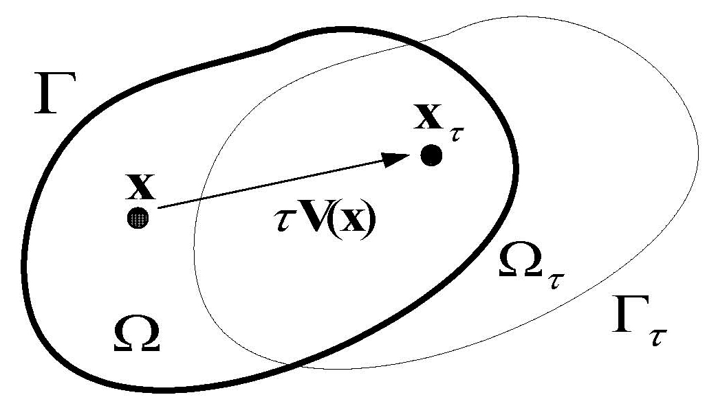
Suppose that only one parameter τ defines a transformation T. The mapping is given by . A design velocity field that is equivalent to a mapping rate can be defined as(25)
The point-wise material derivative of response z at x∈Ω is expressed as(26)
where z′ and ∇z are the partial derivative and the gradient of z ,respectively.
Taking the material derivative of the governing equilibrium equation, Eq. (20) with respect to the shape design parameter τ , the design sensitivity equation is obtained as(28)(29)(30)
For the accurate evaluation of shape design sensitivity, it is very important to determine an appropriate design velocity field. To maintain the geometric exactness of perturbed NURBS surface, the design velocity field can be obtained directly from the NURBS basis function as(31)
where δBI is the perturbation amount of control points between the original and the perturbed designs. The velocity field due to the perturbation of single control point M is computed by(32)
Therefore, for a unit perturbation of control point M , the design velocity field is the NURBS basis function itself, which has moreover non-local characteristics depending on the order of the NURBS. Note that the NURBS basis function in this paper is independent of design variables since it is constructed in the parametric domain.
After the isogeometric discretization, the matrix form of the design sensitivity equation, Eq. (27), is expressed as
where is identical to the modified stiffness matrix and the modified force vector is given by(34)
Eq. (33) is explicitly rewritten as
Note that the obtained displacement sensitivity coefficients in Eq. (35) are also C0 continuous.
2.6 Numerical examples
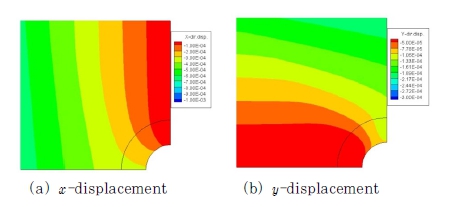
Consider the infinite plate with a circular hole shown in Fig. 4(a). Taking advantage of the symmetry of problem in x- and y-axes, one quadrant of the domain is considered. The multi-resolution model consists of two patches; fine scale patch(blue) and coarse scale patch(red) in Fig. 4(b). Only the fine scale control points are refined to compare the convergence of multi - resolution model with that of uniformly refined model in Fig. 4(c).
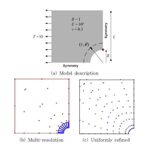
To represent the assumption of infinite plate, the length of plate(L =100) is taken relatively long enough compared with the radius of hole(R =1). In Fig. 5, notice that the x- and y-directional displacements are continuous across the interface in the multiresolution model for a given traction(T =10). This implies that the displacement compatibility condition of Eq. (15) is successfully enforced.
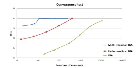
The analytic solution of maximum stress is known to occur at the red spot as shown in Fig. 4(a). Convergence to the analytic solution (σxx=30) can be achieved if the sufficient number of h- refinements is performed. In Fig. 6, as increasing the number of elements, a convergence test is carried out for the numerical solutions by the uniformly refined IGA (red), the multi-resolution IGA(blue), and the finite element(green) models. Quadratic splines are used as the basis function for the isogeometric methods and linear functions for the finite element method. The multi-resolution result converges to the analytic solution faster than any other ones.
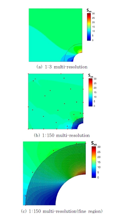
The stress contour is discontinuous across the interface as shown in Fig. 7(a), which is a drawback of the proposed multi-resolution method under the displacement compatibility condition. Even if the fine region is sufficiently refined(1:150 resolution) as shown in Fig. 7(b) and (c), the discontinuity is still persisting. Higher order continuity could be achieved if stronger compatibility requirements are enforced.
To assess the derived isogeometric DSA on the multipatch interface, the cantilever(length of L =8, height of h =2) is considered subject to the traction of on the upper right tip(red dot) as shown in Fig. 8. Material properties are the Young’s modulus of E = 1.0×10¹⁰ and Poisson’s ratio of v =0.3.
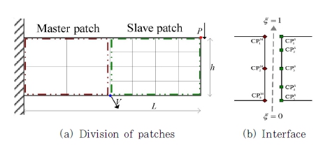
The cantilever model is composed of two patches; the master patch of original coarse resolution and the slave patch of refined resolution using h-refinement. To generate the design velocity field, a design perturbation is made at the middle of bottom(blue point) in Fig. 8(a).
The objective of this example is to verify the accuracy of shape sensitivities along the interface. As shown in Tables 1 and 2, the isogeometric sensitivity in multi-resolution approach shows an excellent agreement with the finite difference sensitivity in each patch.
Table 1
Sensitivity of displacement in master patch
Table 2
Sensitivity of displacement in slave patch
Along the interface, the number of control points in each patch is different in the multi-resolution model.
Consequently, the design sensitivity results should be verified by not the displacement coefficient but the displacement response in contrast to the existing isogeometric DSA method(Cho and Ha, 2000). This comes mainly from the lack of Kronecker delta property in the NURBS basis functions. At the same parametric position on the interface of original and h -refined patches, the control points in each patch have different values even though the response at that position is identical. For instance, in Table 1 and in Table 2 are located at the same parametric position but their sensitivities of displacement coefficients are not identical. However, the sensitivities of displacement responses in Table 3 show that they are exactly identical.
Table 3
Compatibility of displacement response sensitivity on interface
3 Conclusion
We study the local refinement scheme in isogeometric analysis, named multi-resolution approach using multiple patches, and develop shape design sensitivity analysis for the method. Because the method directly uses NURBS data without altering T-mesh, it is well suited to original intent of isogeometric analysis. Through some numerical examples, efficiency and accuracy of proposed method in terms of analysis and sensitivity are shown. Also, the proposed sensitivity analysis possesses the same compatibility along the interface as in the analysis, even though derivative quantities, stress or strain, are discontinuous on the interface. Though solution quality is a little deteriorated due to the constraints, they are fairly acceptable considering the improved results on the region of interest.
