

1. Introduction
2. Methodology
2.1 CAD modeling
2.2 Materials
2.3 Cutting force
2.4 Stability Analysis
3. Results and Discussion
3.1 Maximum stress and displacement
3.2 S-N curve
3.3 Modal analysis
4. Conclusion
1. Introduction
Medical waste(MW) is the main source of pollutants produced by medical diagnosis, treatments, implants, and pharmaceutical residues(Chartier et al., 2014; Ilyas et al., 2020). According to World Health Organization(WHO), about 15% of total healthcare waste is regarded as hazardous infectious waste, while remaining as non-hazardous waste(WHO, 2018). However, the volume has a drastic increase after the COVID-19 outbreak. In Wuhan, China, the MW increased from 40 tons/day to 240 tons/day ,and in the US, it increased from 0.4 million tons/month to 2.5 million tons/month after the pandemic(Ilyas et al., 2020). Similarly, in South Korea, approximately 295 tons of MW was generated from February 2020 to March 2020, and was further increased to 20 tons per day in April 2020(Rhee, 2020; UNESCAP, 2020). Most of this MW is generated from hospitals(61%), quarantine centers(21%), isolation centers of COVID-19 patients(13%), and community treatment centers(Minister of Environment, 2020; Rhee, 2020).
The effective management of hazardous MW is highly imperative to prevent the risk of infection transmission by pathogenic microorganisms. Gastroenteric, respiratory, ocular, and skin infections are some of the potential infections caused by exposure to MW(Chartier et al., 2014). Moreover, the COVID-19 reproductive number may also increase as a consequence of exposure to COVID-19 MW, which includes surgical masks, gloves, personal protective equipment, and other contaminants(Li et al., 2020; Singh et al., 2020; Zhao et al., 2020). The core principles and right resource investment to reduce such health adversities and also environmental concerns are highlighted by WHO in June 2017(Datta et al., 2018). Hence, proper disposal of MW with disinfection treatment is mandatory. Table 1 shows a comparison of various disinfection technologies used to disinfect medical waste. Incineration is the widely used disinfection method which is based on high-temperature combustion of MW at 800°C to 1200°C(Datta et al., 2018; Wang et al., 2020).
Table 1.
Comparison of various MW disinfection technologies(Thind et al., 2021; Wang et al., 2020)
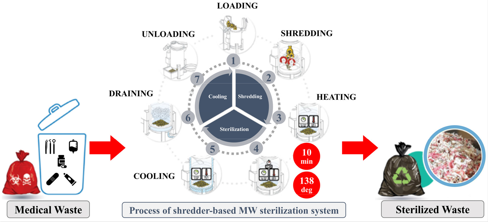
Although traditional incineration can deal with the high capacity of MW constantly with exceptional volume reduction, however, it possesses severe health and environmental concerns. In recent research, Bae et al. concluded that there is a relatively higher risk of asthma for people living in the 2km range of incinerator facilities in Seoul(Bae et al., 2020). This is due to the irreversible harm generated by the ash, which contains a high level of carbon footprints, dioxins, chlorines, mercury, and other heavy metals(Kim et al., 2018; Liu et al., 2018). High transportation costs and shortage of landfill sites are some other problems associated with incinerators(Kim and Jeong, 2017; Tsakalou et al., 2018). Therefore, it is advisable to use compact sterilization-based shredding technology(as shown in Fig. 1) to overcome the shortcomings of the traditional MW disinfecting technologies(Chaiyat, 2021; Hong et al., 2018; WHO, 2002). Shredder integrated disinfectant treatment technology exposes more area of the MW to disinfectant in the sterilization process as the volume of MW is reduced up to 90% by the shredder (Corum et al., 2015; Chaiyat, 2021; Kythavone and Chaiyat, 2020). Consequently, effective disinfection is obtained with minimal emission of pollutants(Gautam et al., 2010).
The current study aims at designing an effective shredder system for MW sterilization. The purposes are twofold: designing the MW shredder in commercial CAD package; and predicting the structural stability of shredder blades through static, fatigue, and dynamic analysis on commercial FEM package, ABAQUS. This article deals with establishing the numerical model of shredder blade based on the loading conditions associated with cutting MW. Then, the static analysis procedure was adopted to evaluatethe stress, strain, and displacement at the cutter edge. The life of the shredder blade was predicted using the ABAQUS FE-SAFE module, and SN-curve was generated based on the actual load cycle. Modal analysis was also performed to check the dynamic stability of the shredding system. Finally, the potential of using such shredder-based sterilization technology has been analyzed in terms of the obtained results.
2. Methodology
This section introduces the CAD models, materials, and the complete scheme of loads and boundary conditions considered in the current study. Moreover, the complete methodology to perform static, fatigue and dynamic analysis is also discussed in this section.
2.1 CAD modeling
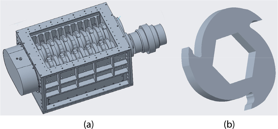
The blade geometry and 2D CAD drawings were designed at Samyoung Plant Co., Ltd, South Korea. The drawings were then converted into 3D models using CAD software. The assembled view and the blade geometry of the developed models are shown in Fig. 2.
2.2 Materials
Lack of knowledge regarding material, its behavior and associated additional costs for fabrication of the structure may result in improper material selection. Hence, the material selection is purely based on the design requirements including low density, high strength and stiffness, and high fatigue resistance. Hardox- 550 is used as the blade material due to its low wear and high mechanical performance. Mechanical properties of Hardox-550 are shown in Table 2(Oxelösund, 2002; Voicu et al., 2020). SS400 and S45C are used for most of the remaining components, as they are widely used for machine structures. FC250(grey cast iron) is used in bearing cover and housing. For the rest of this study, H-550 will adopted as the blade material.
Table 2.
Material properties of HARDOX-550 blade material
| HARDOX 550 | |
| Elastic Modulus | 200GPa |
| Poisson Ratio | 0.3 |
| Density | 8100kg/m3 |
| Yield Strength | 1400MPa |
| Tensile Strength | 1700MPa |
| Hardness | 550HBW |
2.3 Cutting force
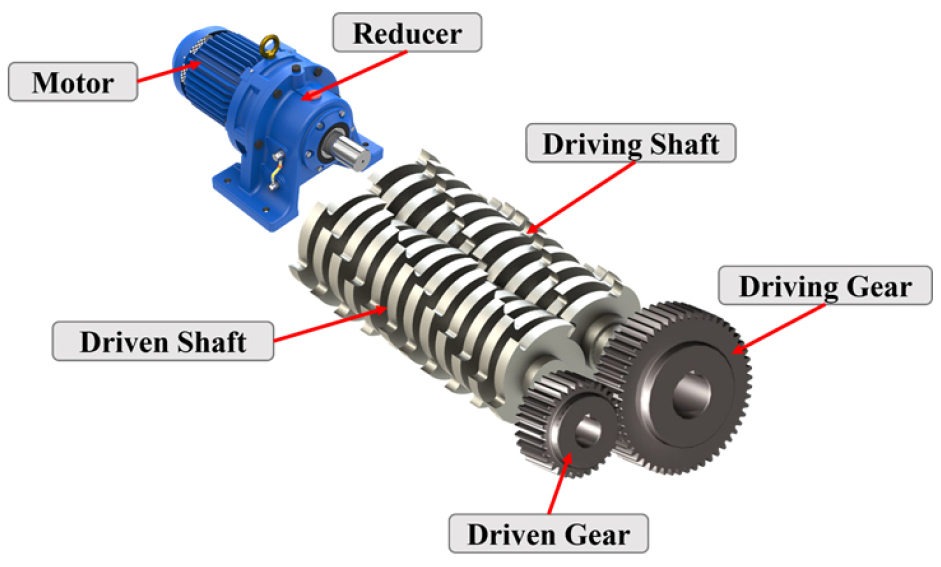
The prediction of the cutting force is based on the pre-defined motor specification. Fundamental machine design expressions were used to calculate the cutting force from motor power. The schematic representation of the shredder system transmission for cutting force calculation is shown in Fig. 3. The torque for 37kW (1500rpm) motor given in the drawings was evaluated using the following expression:
Then, based on the 1:21 reducer the torque transmitted to the driving shaft was evaluated and converted to force using blade radius. This came out to be 38.8kN, which is the cutting force produced at the blade edge and has been used to further analyze the shredder system.
2.4 Stability Analysis
The shredder blade shown in Fig. 4(b) was used to perform the static analysis. The developed CAD model was imported to the ABAQUS in IGES format. Material properties of H-550 were assigned to the blade. Inner surfaces of the blade were assigned encastre constraint to restrict their motion in all degrees of freedom(DOFs). Pressure force of 38.8kN was applied to the blade surface, and a static general step was used with the output request for maximum von-mises stress, total strain, and maximum displacement.
The same model generated in the elastic stress analysis step was then imported to the ABAQUS FE-SAFE module to perform fatigue analysis. Same material properties were added in the FESAFE module, and the time-dependent fatigue load cycle was defined.
Dynamic analysis was performed on the cutting blades mounted on the shaft. Both ends of the shaft were fixed and, interaction between the blades and shaft surface were defined using the contact pairs in ABAQUS. Due to the complex blade and shaft geometry, 10-node quadratic tetrahedron(C3D10) elements were used to mesh the model.
3. Results and Discussion
3.1 Maximum stress and displacement
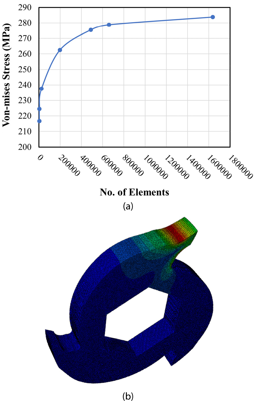
The 8-node linear brick elements(C3D8R) were used to perform linear elastic stress analysis at different mesh sizes. The mesh convergence study for the static analysis is shown in Fig. 4(a), where von-mises stress is plotted against the number of elements in the finite element model. It was observed that the analysis converges at the mesh size of 1.35 with 659,448 elements. The maximum stress of 279MPa was produced at this mesh, as shown in Fig. 4(b), with the maximum displacement of 0.181 mm. The results also revealed that the maximum elastic strain produced in the system is 1.46×10⁻³. Since the yield strength of blade material is 1400MPa, FOS of 5 was observed, which is beneficial in reducing the cause of potential failure in shredder blade.
3.2 S-N curve
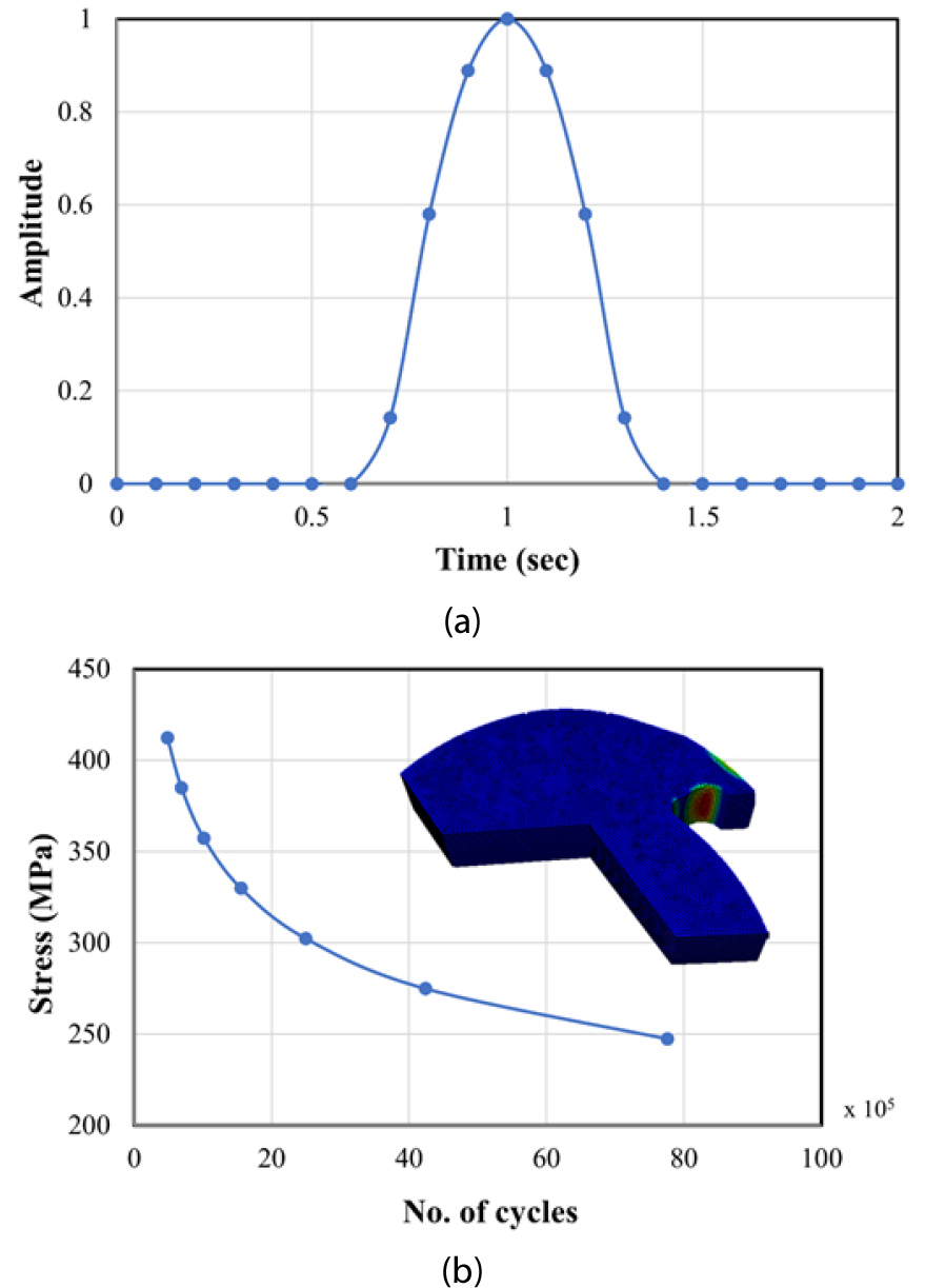
Using the specified speed of the shaft(30rpm), each blade has contact with MW once every 2 seconds, which is used to develop the fatigue load cycle. The time-dependent fatigue load cycle used for fatigue analysis is shown in Fig. 5(a). Since one edge of the blade is used at a given time to cut MW, the work cycle of only that blade has been used in the fatigue analysis to reduce computational cost. The S-N curve for the blade is shown in Fig. 5(b). It has been observed that at the maximum stress (279MPa) evaluated in static analysis, estimated life of the blade is 2.3×10⁵ cycles. Also, as the load is reduced by 10% in each increment, number of cycles were increased. Endurance limit has been achieved at stress less then 240MPa, which corresponds to the 35kN load. Moreover, shortest life of 4.8×10⁵ cycles has been predicted at the stress of 412.4MPa, while any increase in stress will further reduce the life of the blade.
3.3 Modal analysis
Modal analysis has been performed on both driving and driven shafts to determine the natural frequencies of the blade-shaft system and their mode shapes(Sohn and Kim, 2015).
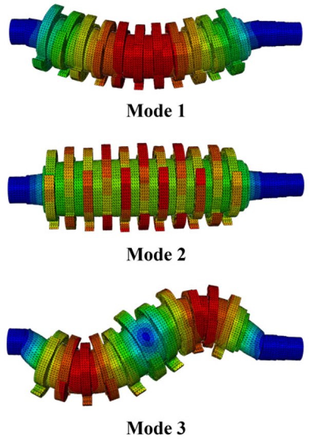
Table 3 shows the modal frequencies of the driving and the driven shaft. Driven shaft being operated at slightly lesser speed has marginally lower modal frequencies. However, the lowest modal frequency of 13Hz, equivalent to 780rpm is much higher than the operating speed(30rpm) of the shaft. Therefore, the structure is dynamically safe for the intended operation. Also, similar mode shapes were observed for both the shafts. Initial mode shapes of the driven shaft are shown in Fig. 6. Mode-1 indicates the first bending mode at 13Hz, the torsional mode (Mode-2) can be observed at 35.7Hz, and Mode-3 indicates the second bending mode at 49Hz. These observations imply the reliability of the shredder system for the designed loading conditions.
4. Conclusion
The shredding system is the key component of the medical waste sterilization system, with the blades being the most sensitive part of such systems. Taking the 37kW shredder system, we performed stress analysis and predicted the fatigue life of the designed cutting blade. Moreover, dynamic analysis was performed to predict possible failure due to resonance. According to the maximum cutting load subjected to the blade, equivalent maximum von-mises stress was obtained(279MPa), which came out to be much less than the yield stress of the blade material. FOS of 5 was achieved, hence meeting the static strength requirement of the system. The fatigue life at this maximum load using the time series fatigue load spectrum is about 4.23 million cycles. The durability of the shredder blade with varying forces was also proved using the SN curve. Furthermore, the first natural frequency of the system was generated at 13Hz using the dynamic analysis, which is much higher than the operational frequency of the system. Hence, all the design requirements were achieved, and the proposed methodology verified the effectiveness and feasibility of the shredder system to be used in the medical waste sterilization system.
