

1. Introduction
The common underlying driver for ferries and freight vessels are greater speed or greater payload in order to make the mode of transport more commercially attractive for passengers and high value cargoes. This makes the weight of the ships very important design task, and as a consequence there is greater incentive for increased use of lightweight structural materials(Noury et al., 2002).
The main lightweight materials available to ship designer are aluminium alloys and fibre reinforced plastic(FRP) materials. The tendency to date has been to use the former for the medium-to-large size of vessels and the latter for the small-to-medium size of vessels(Hughes, 1997). Fig. 1 shows a plot of the specific stiffness and specific strength characteristics for a range of structural materials. As can be seen in Fig. 1, even the most basic form of FRP, namely chopped strand mat(CSM) laminate, has a higher specific strength compared to steels and aluminiums. Stiffness is an issue when glass based FRP materials are considered. However, this disadvantage can be overcome by the use of carbon based FRP materials, which demonstrate the highest specific stiffness among the structural materials.
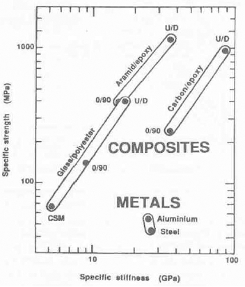
Fig. 1
A comparison of specific strength and specific stiffness of structural materials(Gibson, 1993)
One major inhibiting factor with respect to the wider use of FRP materials in commercial ships is the cost of producing a hull, because it requires an expensive mould usually built from steel or aluminium. Thus the cost of the hull mould places a practical limit on the maximum size of vessel which can be economically produced. As a result there are few all-FRP vessels above 30m in length.
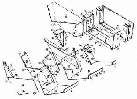
There is therefore a need to devise new forms of FRP hull construction that significantly improve construction speed, and cost. One approach is to construct the hull out of factory-made pre-formed modular structural elements, some of which may be flexible enough to be bent and assembled in such a way as to generate the curved surface of a hull form. Such a method of construction, first proposed in 1975 and shown in Fig. 2(Nicoll, 1975), would eliminate the need for a hull mould thus reducing fabrication costs. The modular hull could be over-laminated with a hand lay-up or vacuum-infusion methods to provide additional structural integrity or allow local variations in thickness and fibre lay-up to suit local stress.
To make such construction method fully effective, it is crucial to have simple but efficient joint capabilities. Kim et al.(1995) introduce two different step joints: one is the step joint created by laminating layers and another is machined step joint on the surface of a laminate. For both joints, static and fatigue tensile strengths are investigated. Kumar et al.(2006) investigate the tensile strength of scarf jointed unidirectional carbon and epoxy materials. Similarly, Yoo et al.(2016) consider v-scarf in-plane bonded joint for carbon and epoxy materials and perform tensile strength test. Bonded single-lap and double-lap joints are also studied experimentally(Li et al., 2015), and joint design parameters like overlap length, adherend thickness and width, and scarf angle are considered in their experiment programs. All these briefly summarised in-plane bonded joint works are based on the traditional joint manufacturing method which requires labor intensive open moulding process such as hand lay-up.
Therefore, this paper deals with the development of a simplified and automated jointing method for the modular FRP hulls, particularly with regard to in-plane bonded joints connecting two panels. A concept of ‘moulding-in’ is utilised and, from this, step, scarfstep and scarf joints at the edges of panels are developed, which minimise the need for panel edge preparation prior to bonding. Test specimens are manufactured using vacuum assisted resin infusion method(Professional Boatbuilders, 2001), and their strength assessment is performed for tension and flexural strengths through experimental and finite element modelling work.
2. Joint design
A major requirement in joint design is to maintain the integrity of the overall structure when the joint is present. This structural integrity can be defined in strength in tension or compression or shear or bending. Another requirement that needs to be considered at the design stage is the economics of producing the joint. In large and complex structures the joints can constitute a significant proportion of structural weight and their manufacturing can be expensive. It is necessary to ensure that material and labour requirements are kept to a minimum and the technology used to produce the joint is compatible with that used elsewhere in the structure.
In-plane joints are used whenever two structural elements need to be jointed. Typical examples of the in-plane joints are scarfed or lapped joints. The former is usually adhesively bonded while the latter may be bolted, adhesively bonded or both. These joints are frequently used for the single skin laminates and the sandwich skin laminates.
2.1. Manufacturing the joint edges
Traditional FRP hull jointing configurations such as step and scarf joints, and, combination of the two, scarf-step joint could potentially be used for a modular hull construction. These joint options are selected in this paper so that the performance of the moulding-in connection capability could be compared with that of traditional techniques.
Aluminium moulds based on moulding-in concept are designed and made to create the selected joint option edges within the vacuum assisted resin infusion process. Figs. 3 and 4 show the dimension and pictures of step, scarf-step and scarf joint edge moulds for sandwich panels, respectively.
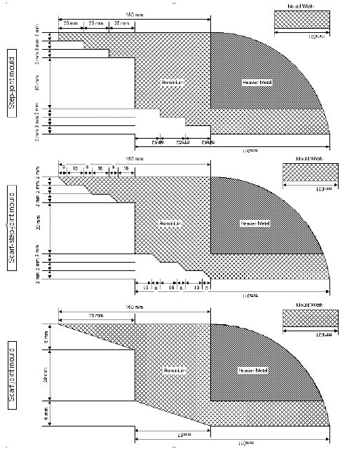
In case of the sandwich cores, butt joint option is applied. Step joint edge has three steps and each step has 25mm in length that provides a larger bonding area than that of a butt joint. Scarf-step joint edge has three 9mm scrafing and 16mm stepping to create a greater area in shear than the step joint edge. Its scarf and step combined edge length has 25mm the same as that of step joint edge. Scarf joint edge has the traditional scarfing shape and it has 75mm in length equal to the total joint edge length of the step and scarf-step joint edges.
2.2. Production of jointed sandwich panels
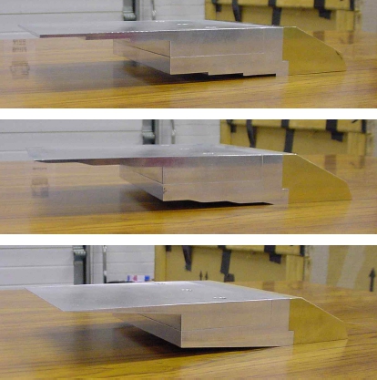
Using the moulds for step, scarf-step and scarf joint options, the joint edges of sandwich panels are manufactured. E-glass woven roving mats and epoxy resin are used as building materials for the sandwich skin laminates, and PVC foam is used for the core of the sandwich panels. Under the vacuum assisted resin infusion process, 12 layers of E-glass woven roving mats are laminated to achieve the joint edge thickness of 6mm, and one sheet of ATC Core-Cell A500 having 20mm in thickness is used for the core. Fig. 5 shows the manufactured joint edges for the sandwich panels.
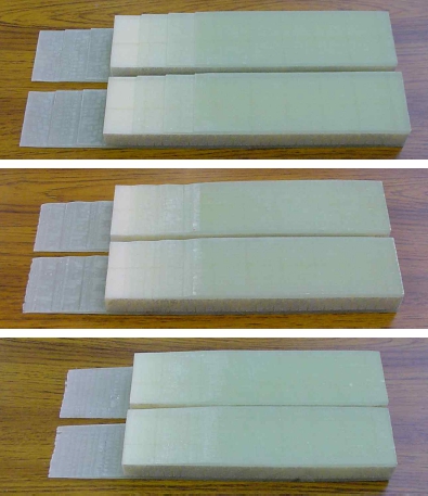
Fig. 5
Manufactured joint edges of the sandwich panels : step(top), scarf-step(middle), and scarf(bottom) joint edges
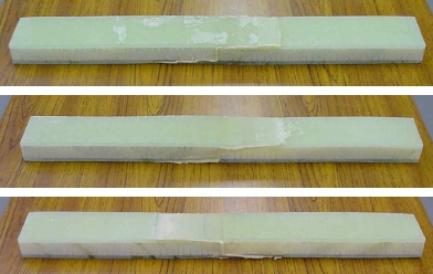
In jointing two joint edges together, Araldite 2015 (Huntsman, 2017) is used. This structural adhesive material is toughened epoxy adhesive that is very thixotropic and gap filling up to 10mm. Araldite 2015 has the tensile strength of 30MPa and the averaged shear strength of 22MPa, and is particularly suited to bonding FRP materials.
The bonded sandwich panels are placed in the oven at 40°C for 4 hours for full curing as instructed according to Araldite 2015 technical data sheet. Fig. 6 shows the pictures of the bonded sandwich panels having step, scarf-step and scarf joint edges.
3. Experimental assessment
Tests are performed with respect to the jointed sandwich panels and the jointed skin laminates. For the jointed sandwich panels, 4-point bending test is considered, while both tension and 4-point bending tests are considered for the jointed skin laminates. Tension test allows an indication of the shear strength capacity of the joint, and 4-point test enables an assessment of the flexural resistance. The tests also allows a check on fabrication efficacy, i.e. whether the failure is in the jointed region or within the laminate itself. Within a joint, it is possible to study adhesive versus cohesive failure.
4-point bending test specimen of the jointed sandwich panels are prepared according to ASTM C 393(2016). It should be mentioned that the size of a flat membrane frame used in the vacuum assisted resin infusion process has 0.9m(width)×0.9m(length) area, and this makes difficult to follow the recommended test specimen size in ASTM C393. Therefore the size of the jointed sandwich panel test specimen is decided as much as close to ASTM C393 recommendation. Fig. 7 shows the schematic view of the test specimen.
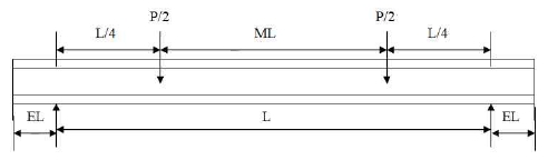
Where, L=400mm, W=50mm, tinner skin=6mm, touter skin=6mm, tcore=20mm, EL=50mm, ML= 240mm, and L/4=80mm, respectively.
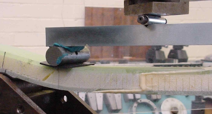
The test is performed according to the test procedures in ASTM C393. Results are shown in Table 1 for control, step, scarf-step and scarf joint options. Here, control option has no joint edge and it is produced from the same manufacturing technique used for the jointed edge options. All the jointed specimens are failed at the core due to shear. Fig. 8 shows the picture of the core shear failure of scarf joint option as an example.
Table 1
4-point bending test results of control and jointed specimens
| Specimen | Failure load (kN) | Failure deflection (mm) | Failure mode |
|---|---|---|---|
| Control | 10.2 | 23.0 | Core shear |
| Step joint | 10.2 | 20.0 | Core shear |
| Scraf- step joint | 9.1 | 17.6 | Core shear |
| Scarf joint | 8.4 | 16.0 | Core shear |
Failure never occurs at the skin laminates where the three joint options are introduced. This is happened due to the relatively thick/strong skins and thin/ weak core.
Among the jointed specimens, step jointed specimen shows the highest failure load followed by scarf-step and scarf jointed specimens. Although this test could not show the flexural strengths of the different joint options, all the jointed specimens successfully demonstrate reliable bonded joint capability.
After 4-point bending test on the jointed sandwich specimens, the three jointed skin laminate specimens are prepared from the corresponding jointed sandwich panels by removing their cores and acquiring their jointed skin laminates only. Based on ISO 527-5 (2009) and ASTM D 790(2017), four tensile and four 4-point bending test specimens are obtained from the acquired jointed skin laminates. The dimension of the tensile jointed skin laminate specimens are 200.5mm (length)×25mm(width)×6mm(depth), and the specimens are loaded in tension using an Instron screw driven test machine. The dimension of the jointed skin laminate specimens for 4-point bending test is 350mm (length, TL)×25mm(width)×6mm(depth), and its schematic view is shown in Fig. 9.
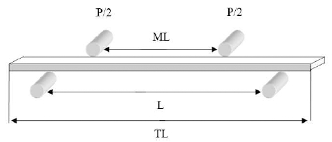
Where, L=220mm, and ML=110mm, respectively. Test results are summarised in Table 2 for tension, and Table 3 for 4-point bending.
Table 2
Tensile test results of control and jointed skin laminates(averaged values)
| Specimen | Failure stress* (N/mm2) | Failure stress** (N/mm2) | Failure load (kN) |
|---|---|---|---|
| Control | - | 475.50 | 47.6 |
| Step joint | 10.22 | 127.75 | 12.8 |
| Scarf-step joint | 10.22 | 153.25 | 15.3 |
| Scarf joint | 11.63 | 218.00 | 21.8 |
Table 3
4-point bending test results of jointed skin laminates(averaged values)
| Specimen | Quarter span deflection(mm) | Failure stress (N/mm2) | Failure load (kN) |
|---|---|---|---|
| Step joint | 12.7 | 272.25 | 0.66 |
| Scarf- step joint | 16.3 | 272.25 | 0.66 |
| Scarf joint | 14.6 | 309.38 | 0.75 |
Tensile failure load for control specimen is 47.6kN, while step, scarf-step, and scarf jointed skin laminate specimens achieve 12.8kN, 15.3kN, and 21.8kN, respectively. From this result, it can be said that scarf joint is the strongest joint option among the three joint options. Scarf-step joint is stronger than step joint but the difference between them is marginal. This finding can be confirmed by calculating failure stresses at the jointed areas of the three joint options. In average, scarf joint option has 11.63kN while step and scarf-step joint options have the same failure stress of 10.22kN, which is lower than that of the scarf.
Failed specimens are closely examined to understand their failure mechanism. It is apparent that a high stress concentration occurs at the step, because of the high density of delamination is observed. Delamination is also observed at the scarf-step but not to the same extent. The reason for the failure here is the reduced area in shear because of scarfing. Scarf joint option shows virtually no delamination indicating cohesive failure, and yields the highest jointed strength.
In bending, the failure stress of scarf joint option is 309.38MPa, while step and scarf-step joint options show the same failure stress of 272.25MPa. This reveals that scarf joint option is the strongest one among the three joint options. It should be mentioned that four control specimens are never failed even under 3 times the load applied to scarf joint option. The test is abandoned due to excess deflections making it impossible to perform. For this reason the results of the control specimens are not included in Table 3.
All the jointed skin laminate specimens are failed suddenly thus it is nearly impossible to say that how the failure initiates and what is the failure mode. After the test, the failed joint sections are carefully examined, and it can be said that the failure is occurred at the interface between the adhesive layer and the adherend. From this observation, the jointed specimens are failed because of adhesive failure due to the peel forces induced in bending.
4. Finite element modelling assessment
4.1. Development of finite element models
A standard, commercially available finite element (FE) analysis package, ANSYS is used as numerical solutions for control and jointed skin laminates of sandwich panels. SOLID46 element type is employed in the development of the FE models. This particular element produces the most accurate results when the global structural responses of composite structures are concerned. SOLID46 is a layered version of the 8-node, 3-D element with three degrees of freedom per node(UX, UY, UZ). It is designed to model layered shells or layered solids and allows up to 100 uniform-thickness layer per element. An advantage with this element type is that it can be stacked several elements to model more than 100 layers to allow through-the-thickness deformation slope discontinuities. SOLID46 has an effective stiffness in the transverse direction permitting non-zero stresses, strains and displacements in the transverse direction. In the FE models, the geometry of the experimentally tested jointed skin laminate specimens is used. Table 4 shows the materials properties used in the FE modelling.
Table 4
Material properties of E-glass woven roving mat/epoxy and Araldite 2015
| E-glass woven roving mat/epoxy(GPa) | Aradite 2015(GPa) | |
|---|---|---|
| E11 | 6.60 | 2.0 |
| E22 | 6.49 | 2.0 |
| E33 | 4.20 | 2.0 |
| G12 | 2.75 | 0.9 |
| G13 | 2.75 | 0.9 |
| G23 | 2.75 | 0.9 |
| ν12 | 0.097 | 0.25 |
| ν21 | 0.097 | 0.25 |
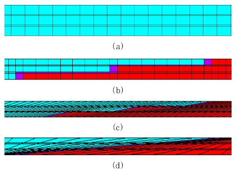
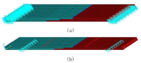
The jointed sections of the developed FE models for control and jointed skin laminate specimens are shown Fig. 10. It should be mentioned that fine mesh generation technique is applied to the jointed section areas to avoid unacceptable aspect ratio of the elements and have accurate structural reponses of the joint areas. The full views of step jointed skin laminates subjected to tensile and 4-point bending loads are shown in Fig. 11 for demonstration purpose.
4.2. Comparison with experimental results
Numerical results from the FE models are compared with those of the experiments for the failure stresses. The averaged failure loads from the experiments are used in the FE models to calculate the failure stresses under tension and 4-point bending. Table 5 shows the comparison of tensile failure stresses at joint failure between the experiment and the FE models.
Table 5
Comparison of failure tensile stresses between the experiment and the FE models
| Specimen | FE models (MPa) | Experiment (MPa) | Failure load (kN) |
|---|---|---|---|
| Step joint | 128.97 | 127.75 | 12.78 |
| Scarf- step joint | 153.49 | 153.25 | 15.33 |
| Scarf joint | 220.12 | 218.0 | 21.8 |
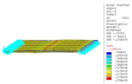
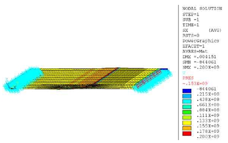
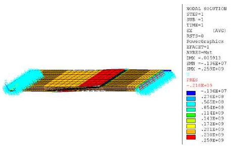
The comparison shows good agreement and this proves that the FE models of the jointed skin laminate specimens subjected to tensile loads are successfully built. Figs. 12~14 show the modelling results of the jointed skin laminate specimens under tension(plain black lines denote undeformed shapes).
Also, Table 6 shows the comparison of failure flexural stresses between the experiment and the FE models.
Table 6
Comparison of failure flexural stresses between the experiment and the FE models
| Specimen | FE models (MPa) | Experiment (MPa) | Failure load (kN) |
|---|---|---|---|
| Step joint | 277.21 | 272.25 | 0.66 |
| Scarf- step joint | 267.04 | 272.25 | 0.66 |
| Scarf joint | 310.67 | 309.375 | 0.75 |
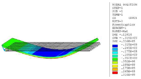
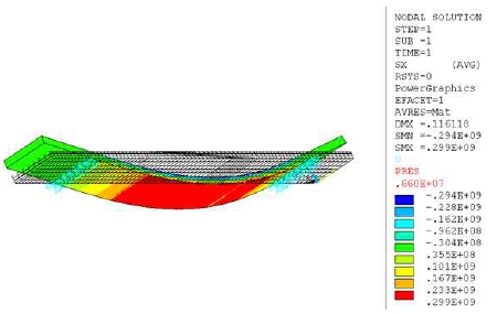
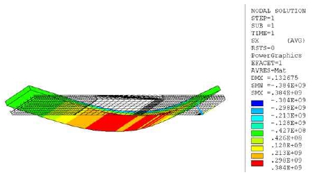
Very good agreement is obtained between the experiment and the FE models. Therefore it can be said that the FE models of the jointed skin laminate specimens subjected to 4-point bending loads are successfully developed as well. The modelling results from the FE models are shown in Figs. 15~17(plain black lines denote undeformed shape). It should be mentioned that the stress values shown along the colour bars in the figures show approximated stress values. Stress values in the middle of the jointed skin laminate specimens can be obtained by listing stress values at the corresponding nodes or elements.
5. Conclusions
This paper deals with the simplified and automated manufacturing of edge details for FRP hull jointing. This is proved by developing a technique based on moulding-in concept, which can create in-plane joint edge details for FRP sandwich panels manufactured from E-glass and expoxy resin. Step, scarf-step, and scarf joint edge options are proposed, and it is shown that these joints act very efficiently in tension showing cohesive failure mode. Under 4-point bending the joints fail at the interface between the adhesive layer and the adherend and this is occurred due to the peel forces induced in bending. The joint type that provides the best performance is the scarf joint, this is similar to that employed in many marine applications. However, shipbuilding industrial production process has three steps: (1) mould panels, (2) produce joint edges manually and (3) bond joint. In the current approach in this paper, steps (2) and (3) are combined by single process. It is shown that with minimum abrading of the surfaces, a suitable key can be produced on the moulded-in surface. Clearly in producing a modular hulls this approach will significantly reduce production time. Moreover, as the joint strength is much greater in bending(the principal loading mode in hull structures), an encouraging signal is provided indicating this approach is feasible for the modular construction of ships.
